Assembly Table: Difference between revisions
Jump to navigation
Jump to search
(Added location of the output) |
No edit summary |
||
| Line 18: | Line 18: | ||
It is 3x3 but requires a 1x1 where the crew operates it. | It is 3x3 but requires a 1x1 where the crew operates it. | ||
[[Frame]]s go in the centre-right tile at default rotation (facing down) and rotate clockwise when the assembly table is rotated. [[Motor]]s and [[Power Coil]]s always go in the centre. The output is always in the opposite corner to the cable connection. | Visually, [[Frame]]s go in the centre-right tile at default rotation (facing down) and rotate clockwise when the assembly table is rotated. [[Motor]]s and [[Power Coil]]s always go in the centre. The output is always in the opposite corner to the cable connection. However, like with all objects, [[Robot Arms|Robot Arm]] can drop off and pick up from any location in the object. | ||
== History == | == History == | ||
{{History|Alpha 4|Introduced.}} | {{History|Alpha 4|Introduced.}} | ||
Revision as of 01:52, 24 June 2023
| Assembly Table | |
|---|---|
 | |
| Grid size | 3 x 3 |
| Power consumption | 1-2 MW |
| Inputs | Power |
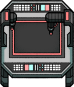
The Assembly Table is used to craft one of:
It is 3x3 but requires a 1x1 where the crew operates it.
Visually, Frames go in the centre-right tile at default rotation (facing down) and rotate clockwise when the assembly table is rotated. Motors and Power Coils always go in the centre. The output is always in the opposite corner to the cable connection. However, like with all objects, Robot Arm can drop off and pick up from any location in the object.
History
- Alpha 4: Introduced.